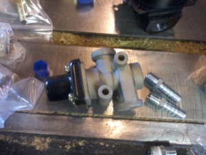
Now, to run this from the tank below the floor up through the bus body and out to the horns needed some other bits to work correctly. First was to put in a pressure regulator, which by adjusting the dial could throttle the pressure to any desired between zero and 200 psi, or however much was in the system.
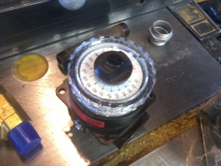 |
| Pressure Regulator |
This was an important consideration that many of the ‘air horn kits’ that I found on-line lacked, as it allows you to quiet your air horns/chimes while you’re in an area with people out and about, rather than a highway with people in vehicles. While there are people who seem to delight in scaring people with a sudden blast of sound from an air horn at maximum pressure, this is horribly irresponsible and potentially dangerous.
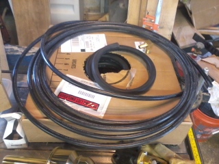 |
| 'Soft' air lines, 1/2" ID in the box and the 3/8" ID around the outside ... |
As the regulator had not only a 1/2“ through port, but also two 1/4“ regulated out ports, I decided to use one of these to run to a pressure gauge that I could mount on the control panel. For this I used mainly a ‘soft’ line of a tough plastic with a 3/8“ interior dimension (but was marketed as a 1/2“ air line), which was not great at turning corners, kinking easily, and causing me to use hard 90 degree elbows to make corners. This was a great way to check what the pressure is in the auxiliary tank, but had the drawback in that when you dial back the regulator to quiet the horn/chime, you only see the regulated pressure, not the whole tank pressure. However, as the regulator dial is mounted behind the driver’s seat, this regulated gauge allows you to change the pressure without looking back for too long while driving. The gauge itself had threads that were
just the size of a removed switch cap on the control panel, so the installation was relatively easy, despite having to route the line between all the other lights and switches on the panel.
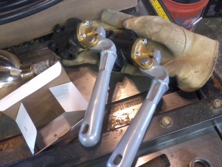 |
| Non-stepped control valves |
The next step after this was to install control valves to actually work the horns. While some people on-line suggested using simple ball valves for natural gas/LP lines, these don’t automatically close, which poses an additional distraction while driving, as opposed to spring-loaded, normally closed valves. I got two non-stepped valves, which are amazingly heavy-duty. Stepped valves have three settings (closed, partly open, and full open), while non-stepped run from closed to full open and all the range in-between depending on how hard you pull on the handle.
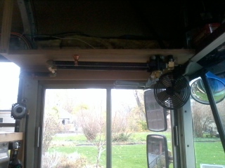 |
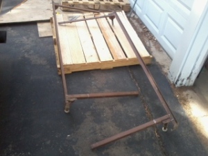
Showing the hard lines from the pressure regulator to the
valves mounted on the shelf to the port side of the captain's chair. |
To counter the possible torque of pulling on one of the handles energetically during a tense moment, I ended up deciding to use hard lines from the regulator to the valves, which made things a bit easier as I needed to split the air line to get to both of the valves.
The lines for the air horns was 1/2” (ID) line to supply the volume of air needed to sound the horn, which can drain the 20 gallon tank fairly quickly, and the hard line was constructed from ‘black’ pipe and brass fittings, and used Teflon tape to seal the threads.
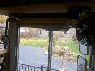 |
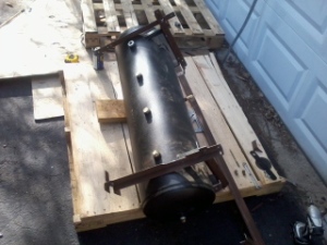
| Another view of the hard lines and valves without so much backlighting. |
These were attached to the shelf that I ended up constructing just above the captain’s chair on the port side, giving easy access to the valve handles, while also not blocking the view. I had expected to put a couple of hanging lines on the handles (like the old truckers had), but the valves ended up being so low and handy that I decided against it.
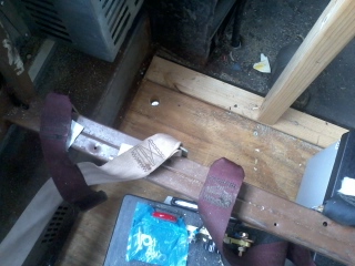 |
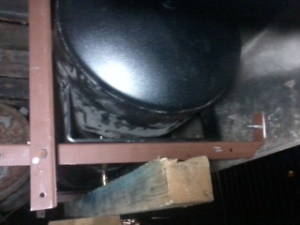
The nice bright dot (of the bright driveway)
is where the air line will come up |
While I went with hard lines from the pressure regulator to the valves, most all of the rest of the line was ‘soft’, a thick, durable air brake line of woven fiber and rubber that could be bent into tight angles without crimping or binding. This allowed for some flexibility of where to run the lines and to easily get the air to a horn along the curved roof. However, it did pose one problem; that of how to run the soft line through the flooring, which was a 20 gauge steel sheet.
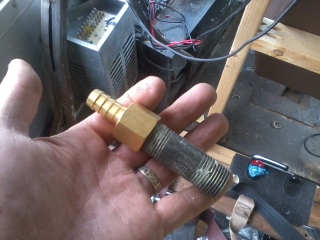 |
| A brass barb fitting on a black iron pipe to go through the floor |
I got around this by using a short ‘hard’ pipe through the floor with flared barbs at each end to attach the pipe and the ‘soft’ line.
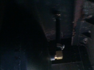 |
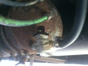
| A dark photo of the connection between the tank and the 'through-the-floor' fitting |
The first air sounding unit I put in was the
air chime. Nicely finished with brass, I wanted to install it with the pipes pointing up, but due to the construction of the lower ‘bell’ housing not having any drainage hole for rainwater, if I had, the air line down to the valve would fill with water and a winter freeze would have been disastrous. So, it got mounted sideways, which still isn’t bad. I ran the holes through one of the plates that I put over the school bus flashers, and piped a hard, brass air line in through the steel. The mounting for this was simple, as the chime had three threaded holes to secure it, so once the exterior of the holes had been ringed with butyl sealant, it went together easily and securely.
 |
| 4 Note Air Chime, Brass (From raneystruckparts.com) |
That said, a word of advice to people who might be considering doing something like this – be careful with your bolts after getting things in place. The butyl sticks to everything, including bolt threads, and can make it tough to get things aligned.
But it certainly can be worth it, as shown by the finished chime, in place:
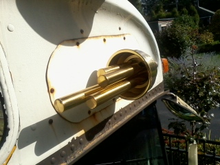 |
| The air chime in place above the driver's eyebrow |
To be continued (in Part III) ...